

Laboratories
Rapid Prototyping Laboratory
Ing. Pavel Růžička, Ph.D.Head:
Workers:
Description:
Fused Deposition Modeling technology
Rapid Prototyping and 3D Printing technologies, under which Fused Deposition Modeling is categorized, enable a physical prototype model to be produced much more rapidly than with classical technologies on the basis of computer data. The computer data can be provided by CAD software packages, 3D scanners, scientific and technical computations or medical imaging systems. The prototype model is created layer by layer, so it is possible to make models of practically any complex geometry. However, the limited range of modeling materials is a major disadvantage.
The Laboratory of Biomechanics is equipped with Fused Deposition Modeling (FDM) technology developed and provided by Stratasys, U.S.A. The Laboratory has a Prodigy Plus machine, see fig. 1, and Stratasys Insight software for production process preparation and control code generation.
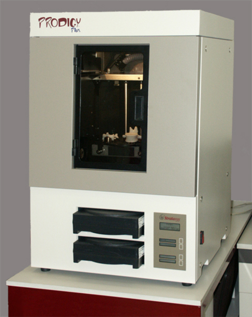
Fig. 1: Stratasys Prodigy Plus
Akrylonitril-butadien-styren (ABS) thermoplastic is used as the modeling material. ABS has material properties, tensile strength 22 MPa and tensile modulus of elasticity 1.627 GPa that allow the use of prototype models as functional prototypes. Prototype models made of ABS can be machined or glued, model surfaces can be finished, polished, painted or vacuum metal plated. Stratasys WaterWorks material is used as the supporting material. It is a soluble material, and the support structures can therefore be dissolved.
The FDM model production process can be briefly described as follows. Modeling and support materials (ABS and WaterWorks soluble) in the fiber form are fed to the extrusion tips, heated up to 280°C, and applied layer by layer. The selectable layer thicknesses are 0.178 mm, 0.254 mm or 0.330 mm. Prodigy Plus is able to build a model up to 203 x 203 x 305 mm in size. Larger models can be made in parts and then glued together.
In the laboratory, the FDM technology is used to support research and development projects in the field of biomedical engineering, but it is in fact general-purpose RP technology. The Laboratory of Biomechanics offers cooperation in rapid prototyped model production.
An example of the RP technology application in the design of a total knee endoprosthesis
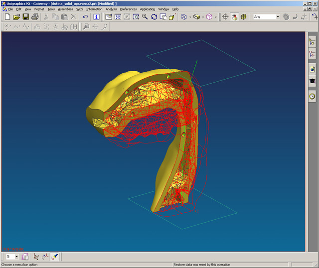
As an example we can demonstrate the production procedure for a prototyped model of a knee joint replacement femoral component. First, a computer model is created by means of Unigraphics - the CAD software package (Fig. 2). The model is fully parametric; therefore it is possible to work with the model geometry in order to optimize the model and fulfill new requirements.
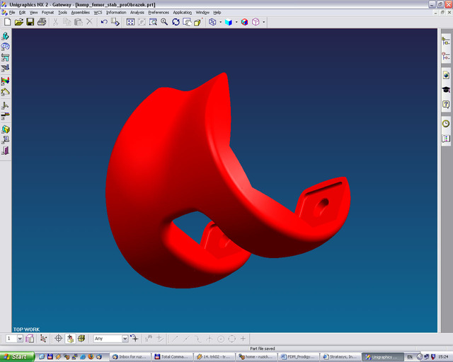
Fig. 2: CAD model of the knee replacement femoral component
Next, the CAD model is exported as STL data. The STL file format is the standard data format for RP technologies; a spatial object surface is represented by a network of triangles. The RP model is prepared by means of Insight software, which was provided with Prodigy Plus. The STL model is sliced into horizontal layers. Then the support structures and extrusion head trajectories are generated. The user can control all preparatory steps, check or modify and create slice curves and support structures, and influence the model building strategy (Fig. 3).
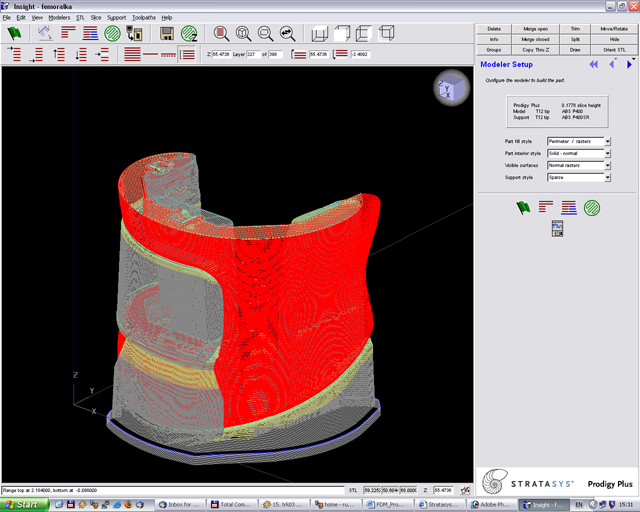
Fig. 3: RP model preparation by Insight software
As a result of working with Insight software, a file containing the control code for Prodigy Plus is obtained. Then Prodigy Plus, following through the control code, builds the RP model without any operator intervention (Fig. 4).
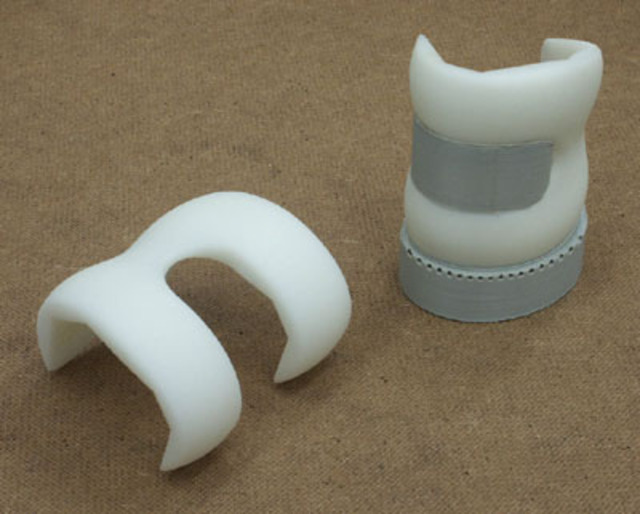
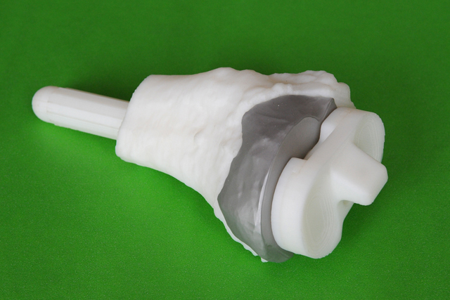
Fig. 4: RP model of a total knee replacement
The RP model of the total knee replacement femoral component is employed in prototype production of the ceramic femoral component of the knee endoprosthesis (Fig. 5). The RP model made of ABS thermoplastic is molded into silicon rubber and the tool obtained in this way is used to produce ceramic semi products by the cold isostatic pressing method.
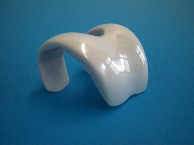
Fig. 5: Knee replacement femoral component made of zirconia ceramics
Benefits of applying RP technology in the medical field and in biomedical engineering
RP technologies contribute to the design process of implants, prostheses, splints or fixtures and medical equipment. The relationship of RP technologies with computer-aided design and the rapidity of the model production enable the design of individual replacements. Several technologies can be used for producing functional prototypes, e.g., FDM technology, and technologies for directly manufacturing individual implants are under development.
RP technologies can also be employed in surgery planning. At the present time medical imaging appliances are available to analyze the situation inside the patient?s body noninvasively. Image data can be acquired by computer tomography (CT) and micro tomography, magnetic resonance imaging and ultrasound. Each method has its advantages and limitations. Data, that supports the physician?s decision, is not limited to 2D images. Modern software instruments are able to analyze the acquired images mathematically, build and display 3D virtual models. There is only one step between a virtual 3D model and a physical RP model. The RP model facilitates surgery planning and communication between physicians. There are materials available that can be made aseptic by UV rays. RP models can be utilized in education, seminars and meetings, or as an instrument for communication with the patient.
More examples of RP models
 |
 |
 |
||||
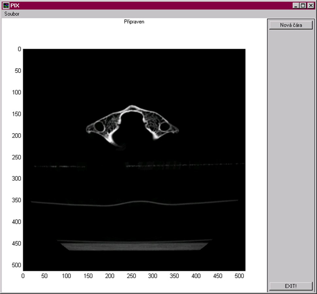
| Fig. 6: An image of one slice through a human cervical vertebra acquired by computer tomography (CT) scanning | Fig. 7: 3D computer model of a human cervical vertebra created by the process of 3D reconstruction of CT scans | Fig. 8: RP model, a copy of a human cervical vertebra | ||||
 |
 |
 |
||||
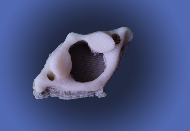
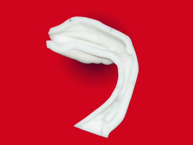
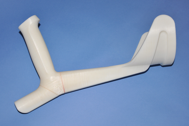
| Fig. 9: CAD model (Unigraphics NX) of the experimental set-up component for experimental analyses of the acoustic field inside a human vocal tract; the computer model of the acoustic cavity was created by 3D reconstruction of magnetic resonance (MR) images, and other construction features have been added. | Fig. 10: RP model of the human vocal tract produced for experimental purposes | Fig. 11: A handle of a forearm crutch, RP model on a scale 1:1, assembled of three parts | ||||
 |
 |
 |
||||
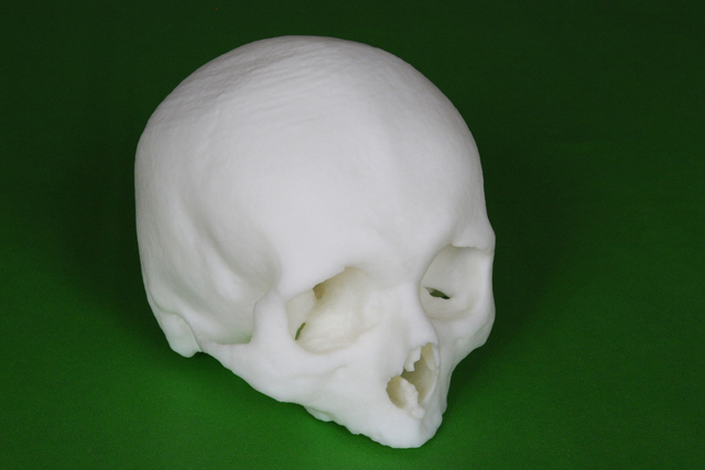
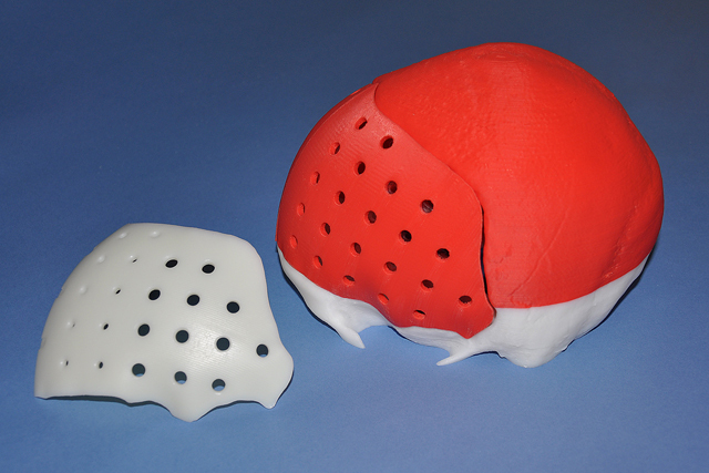
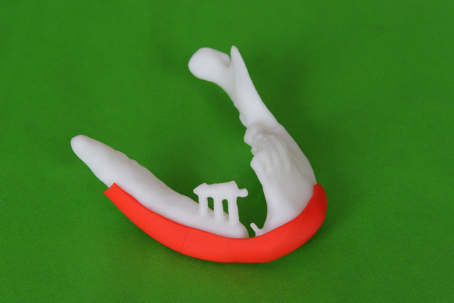
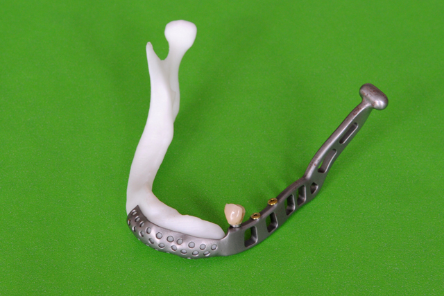
| Fig. 12: A skull model, an example of anatomy model based on medical image data acquired by means of a computer tomograph | Fig. 13: A model of a skull with extensive resection of bone afflicted with tumor, and models of designed implants, on the left the implant made of UHMWPE | Fig. 14: RP models of a tibia and tibial komponent of a total knee prosthesis were used for verification of the individual implant replacing missing tibia tissue | ||||
|
||||||
 |
 |
 |
||||
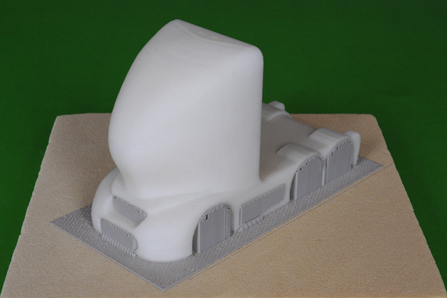
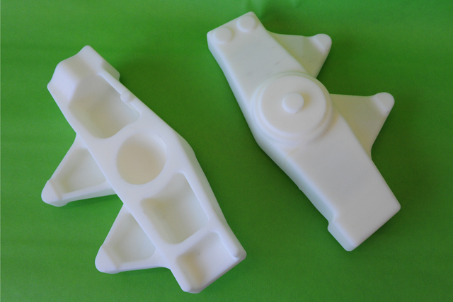
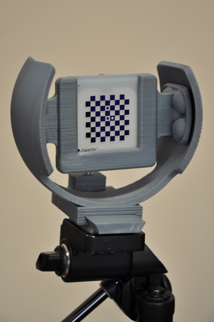
| Fig. 17: Concept of a truck, the RP model intended for measurements of aerodynamic forces in a wind tunnel | Fig. 18: Models of hub carriers of a racing car front axle were used for sand casting mold manufacturing | Fig. 19: A calibration plate positioning device makes calibration process of 3D digital image correlation system easier. The device has been manufactured directly by FDM technology out of gray color ABS thermoplastics | ||||
|
||||||
Stratasys Prodigy Plus - technical specifications
Modeling material: ABS
Support material: WaterWorks soluble
Model build envelope: 203 x 203 x 305 mm
Layer thickness: 0.178 mm, 0.245 mm, 0.330 mm
Input data file format: STL, Parasolid, Unigraphics PRT, STEP, IGES, DXF, ...
Cooperation:
Medin, a.s.; Medin Orthopaedics, a.s.; Saint-Gobain Advanced Ceramics, s.r.o.; ProSpon, spol. s.r.o.; Erilens, s.r.o.; Pal International, a. s.; Gottmark
Projects in realisation
- Research of technical and biological composite materials
- Indentor instrument for cartilage stiffness measurement
- Mathematical model of a lower extremity focused on a knee joint
- Simulation of cyclic loading of total knee replacement where an evaluation of cyclic stress state in tibial plateau is ephasized
- Endurance Test of Stemmed Femoral Component of Total Hip Replacement
- Long Bone Reconstruction and Periprosthetic Fractures Using the Osteosynthesis Materials and the Operation Procedures - Trauma I
- Inovation of French Crutches
- Mechanical properties of osteoporotic bones
- Optical 3D coordinate measuring machine
- Mathematical model of a lower limb featuring an oncology hinge type knee endoprosthesis
- Apllication of ceramics and β-Ti alloy for shoulder endoprostheses
- Revision Endoprosthesis of Acetabulum - FEM Analyses of the augmented replacement.
- The development of intelligent endoprosthesis with automatic early detection of potential failure